Well since the lockup ended and the workshop reopened I've been trying to get in as much as I can, but as usual its a question of finding the time around everything else particularly work as I've changed job role recently so as usual, that sort of explains the length between updates. That and it simply takes time to do all of this.

Anyway, progress. First was some bronze bushing in the levers on the test set to prove what I intend to do. That will wait until the end before I complete it for the set but needed the lever to move correctly in order to ensure things will work. Secondly I finished off some spacers. And thirdly I made some gear change linkage rods of different lengths (just got 4 to finish as I had to wait for some more metal to arrive).

One of the things I didn't get a chance to finish before we all got locked up was the return stopper for the rear brake. Using my mock up I based it on the kit and turned down a 22mm round and put an offset 6mm hole it it for the bolt. Trouble is it looked a bit plain so a 14mm end mill was taken halfway in opposite and in rotation to loose a little weight and add a little feature.

The other thing that needed to be sorted was the lever return spring. Firstly a couple of spacers to offset the spring from the main body with a spring seat added to them were turned down and cut to the right length. I then used
Springs and Things to get an extension spring 30mm long 0.63mm thick and having a 6.3mm OD in stainless which worked quite well. I also placed an order with
ACCU for stainless bolts of the right length as my local dealer isn't doing walk-ins at the moment, though I've not added them all in the photos yet.
[/url]
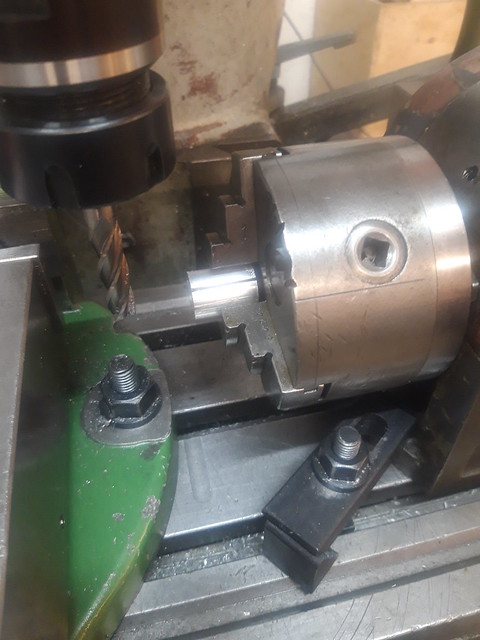
My thoughts then turned to the rear brake arm linkage. The one in the kit wouldn't fit as it was now too short as I'm using the longer swing arm and also didn't reach the lever on a straight path as I've changed the offset of the peg. So I needed to make my own. But before that I noticed a little change I needed to make, the original linkage sits below the swing arm, however that wouldn't work for me and following the kit you need to rotate it to the top and the simplest way to do this is to rotate the brake pin by 180°. The problem then is that the brake wear indicator dial doesn't line up with the markings on the brake plate casting. So I took the pin out and milled off one of the splines so that it then indicates. It was an interesting setup using a dividing head to align the pin with the cutter but it worked and the indicator now indicates.

Next was the linkage, basing it on the kit I ordered some 8mm stainless rod and started prototyping, it took 5 attempts to get where I wanted. I'll save you the detail but it was a combination of understanding the design, getting the bends right, getting their offsets, and keeping it straight, but I got there in the end. I start out with 330mm length of rod and drill and tap a M6 thread in one end, and at this point I can say Stainless Steel is horrendous to work with. Its so tough even to just drill the clearance hole, tapping it gets even worse. Because of the size I'm using a hand tapping set and that turns into a bit of exercise, and the heat it generates is phenomenal. But in the end I get the thread tapped. So now I flip the rod round in the lathe and take 120mm of it down to 6mm and then cut another M6 thread into the the end but only 60mm as the rest of it is needed as a spring seat.

That's all on the mill so next I turn all Arthur Brown and break out the blow torch. Putting a 45° bend in 8mm stainless is simply not possible using a simple 6-10mm pipe bender. However if you heat the rod to a nice cherry colour with a bit of force it is possible. Now I'm sure it is possible to cold bend it if you can apply the force, but I can't, and I know that heating it probably will change some of the properties of the rod, but I don't think it will impact my application. Anyway I set the bender up level in the vice with a height indicator for the end of the rod that helps later in keeping the rod straight and put the first bend in the rod at the end of the spring seat. I then rotate the rod round to put another bend in bringing the rod back straight, this is 40mm from the finish of the first bend or 115mm from end of the internal thread. With that all finished I removed the heat discoloration with some Autosol, 1200 grit sandpaper, and some WD40.

I also decided to make a Stainless Steel brake arm pin for the arm to pivot on, and replace the standard compression spring with a 83mm compression spring 1mm thick with a 9mm OD from Springs and Things that felt like it matched the force of the original. The final thing was to top it off with an adjuster bolt from TCR. Now I have considered making my own but its probably not a good idea to add to the workload as I need to finish the counterbores and then find a solution to the gear change linkage at the engine side. I have an idea and it involves the welder, stay tuned to hear my tales of arc eye...

Oh, and anyone ever done home anodising?